Pump-Simulation node
Usage of Pump-Simulation node
The following node shows the Pump-Simulation node and its respective functions:
Pump-simulation
![]()
This node allows to generate the time series data of a simulated water pump. The two modes in water pump simulation provides the following function:
- Whole scenario simulation
- Real time simulation
Whole scenario simulation
In this simulation mode, each trigger generates time series for the desired past time. It generates one time series object for each second. You can choose the scenario length in the configuration or specify the desired scenario using the property message.scenario.
Real time simulation
In this simulation mode, each trigger generates time series that fill the gap in the last execution, but not longer than 30 minutes (1800 time series). You can specify the next scenario by sending message with the property scenario. The simulation accepts the next scenario but does not send any message.
Using Pump-Simulation node
Example scenario
In F&B industry, pumping liquids is one of the most frequent operations. Disturbance in pumps can cause interruptions in production process and downstream supply chain. If many pumps are in operation, then localizing the error and correction causes unplanned maintenance and costs.
Usage of Industrial Internet of Things during pump operation enables to minimize down times and keep the production running constantly.
Simulating water pump node generates the time series data with three different scenarios like standard, plugging before pump and plugging after pump.
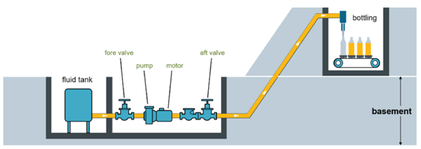
Objective
To monitor the pump installed on the bottling line in a brewery and connected to Industrial IoT. A pump consists of two valves (one before and one after), the pump and a fluid-flow meter as shown in the figure above. The pump is connected to a Siemens SIMATIC IoT2040 and collects the following data points: pressure before the pump (between the left valve and the pump), pressure after the pump (between the pump and the right valve), motor current of the pump, temperature of the motor (stuffing box) and percolation measured by the fluid-flow meter.
Procedure for Whole scenario simulation
To generate the time series data with three different scenarios with simulated water pump, follow these steps:
-
Create the flow as shown below:
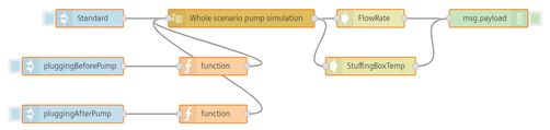
-
Edit standard scenario inject node:
- Name: Standard
- Payload: timestamp
- Edit scenario inject node:
- Name: pluggingBeforePump
- Payload: pluggingBeforePump (string)
- Edit pluggingAfterPump scenario inject node:
- Name: pluggingAfterPump
- Payload : pluggingAfterPump (string)
- Edit pluggingBeforePump scenario function node:
- Code:
msg.scenario = 'pluggingBeforePump';return msg;
- Code:
- Edit pluggingAfterPump scenario function node:
- Code:
msg.scenario = 'pluggingAfterPump';return msg;
- Code:
-
Edit pump node:
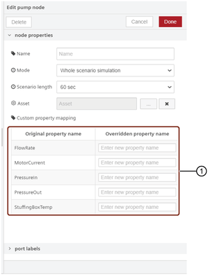
① Overrides the existing property name or specify the custom property name
- Mode: Whole scenario simulation - Asset: Click  to select an existing pump asset or create a new pump asset and click "Ok".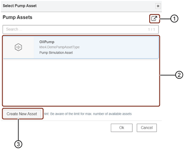
① Opens pump asset in Asset Manager
② List of the pump assets
③ Creates a new pump asset
Using "Create New Asset" button, you can create an asset for the pump in Industrial IoT. -
Edit map node:
- Name: Motor_Current, Passage
- Provided code: { Motor_Current: element['Motor_Current'], _time: element['_time'], Passage: element['Passage']}
- Edit map node:
- Name: Motor_Current
- Provided code: { Motor_Current: element['Motor_Current'], _time: element['_time']}
- Save the flow.
Result for Whole scenario simulation
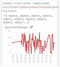
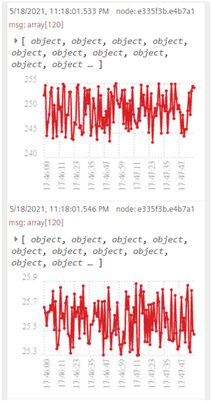
The following graphic shows the graphs in the message payload:
For standard scenario
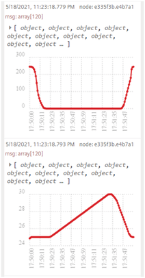
For pluggingBeforePump scenario
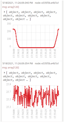
For pluggingAfterPump scenario
Procedure for Real time simulation
To generate the time series data with three different scenarios with simulated water pump, follow these steps:
-
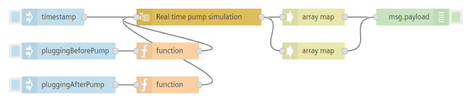
Create the flow as shown below:
-
Edit standard scenario inject node:
- Name: Standard
- Payload: timestamp
- Edit pluggingBeforePump scenario inject node:
- Name: pluggingBeforePump
- Payload: pluggingBeforePump (string)
- Edit pluggingAfterPump scenario inject node:
- Name: pluggingAfterPump
- Payload : pluggingAfterPump (string)
- Edit pluggingBeforePump scenario function node:
- Code: msg.scenario = 'pluggingBeforePump'; return msg;
- Edit pluggingAfterPump scenario function node:
- Code: msg.scenario = 'pluggingAfterPump'; return msg;
- Edit pump node:
- Mode: Real time simulation
- Asset: Select an existing pump asset or create a new pump asset.
- Save the flow.
Result for Real time simulation
The following graphic shows the graphs in the message payload:
For Standard scenario
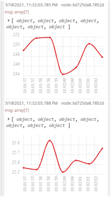
For pluggingBeforePump scenario
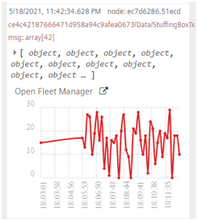
For pluggingAfterPump scenario