Create flows
Introduction to flows
A flow consists of multiple interconnected nodes. The links join the nodes on the working area to form a flow chart. The data enters the flow via input nodes and is processed by other nodes.
Each user can create upto ten tabs in the working area of Visual Flow Creator.
Create a basic flow
Example scenario
The smart city has alternative wind and solar power generation. The dependency on weather sometimes leads to severe constraints.
Objective
The basic flow is to convert data of a weather web service from a JSON format to a JavaScript object structure for further processing.
Requirement
A weather forecast web service supplies information on wind speed, amount of sunshine and temperature.
Procedure
To create a basic flow, follow these steps:
- Move an "input" node to the working area using drag-and-drop.
- Repeat step 1 with "function node" "http request", "function node" "json" and "output node" "debug".
-
Interconnect the nodes. The following graphic shows the connected nodes:

-
Double-click the "http request" node.
- Select the "GET" method in the drop-down menu.
-
Enter the API Call URL with the corresponding data of a weather web service. The graphic below shows the parameters for the "http request" node:
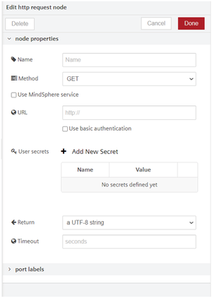
-
To start the flow, click the blue button to the left of the "timestamp" node.
Result
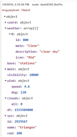
You have created a flow in which weather data from a web service can be retrieved via an "http request" node.
The data is supplied in JSON format. In order to view the data in a "debug" node and evaluate it with JavaScript, a conversion to an object structure takes place using a "json" node.
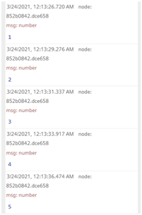
The graphic below shows the output of the flow in the log area:
Debug flows
Using a debug node
To ensure correct execution and data processing of a flow, you can check the flow with a debug node. You can deactivate the debug node like an output node using the green button on the right. Deactivation of a debug node helps you to reduce the number of debug messages from multiple debug nodes.
To fully display the properties and contents of messages in the debug window, you must set the "Output" to "complete msg object" in the properties of a debug node. The debug window then shows the complete "msg-object" content, for example, can include the following fields:
- topic
- payload
- _msgid
You also have the option of displaying any other property (msg.payload).
Debug window
The node ID identifies the node in the debug window. A click on the node ID highlights the corresponding node in the working area. The selection helps you associate the corresponding node with the message in the debug window. The debug window displays important information regarding the data processing and a preview of the message or array output.
The debug window can format arrays and objects in order to improve readability. For timeseries, an additional chart gets added which visualizes the time series data.
Copy flows
You have the option of copying nodes between multiple flows. For this purpose, you can select nodes in a flow and copy them to the clipboard. You can paste the nodes from the clipboard in a new flow.
Procedure
To copy a flow, follow these steps:
- Select the flow you want to copy.
- Open the flyout menu in the main navigation.
- Open the "Export nodes to clipboard" window under "Export > Clipboard".
- Select the export parameters, for example "selected nodes"
- To complete the export, click "Export to clipboard".
- Open the flow tab where the flow is to be copied.
- To paste the flow, open the flyout menu in the main navigation.
- Click "Import > Clipboard".
- Click inside the "Paste nodes here" window in the "Import nodes" window.
- To paste the nodes, press the key combination CTRL+V.
- To import the flow, click the "Import" button.
- Place the flow in the working area.
Note
Inside an instance from VFC, nodes can simply be copied by using CTRL+C and CTRL+V
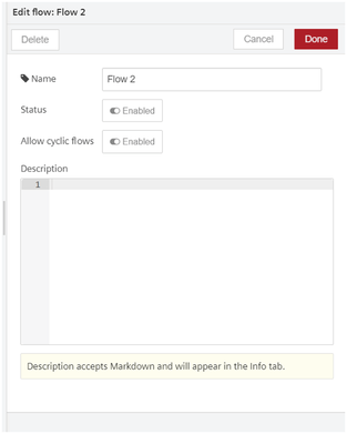
Allow cyclic flows
This feature can execute the cyclic flows for each tab individually in Visual Flow Creator. The “Allow cyclic flows” can be enabled or disabled by using the toggle button at the edit flow tab properties.
Example
The below given is an example to execute the cyclic flows using delay node, follow these steps:
-
Design the flow as shown below:
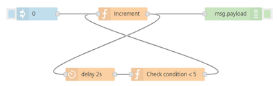
-
Edit inject node properties:
- number: 0
- Edit function node properties:
- Name: Increment
- Language: javascript
- Code: msg.payload++; return msg;
-
Edit function node properties:
- Name: Check condition < 5
- Language: javascript
- Code:
if (msg.payload < 5) { return msg; } -
Edit delay node properties:
- Action: Delay each message
- Fixed delay
- For: 2 seconds
Note
If you proceed to save and deploy the flow, a notification will be displayed with the message "Deploy failed: cycles are detected. This can lead to high compute hours consumption!"
6.Edit flow tab properties:
- Allow cyclic flows: Enabled
7.Save and execute the flow.
Result
The output will be displayed in the debug tab.